Back to Basics — Network Protocols: Can you understand software architecture without these concepts?
Protocols and standards make networks work together. Protocols make it possible for the various components of a network to communicate with each other, and standards make it possible for different manufacturers network components to work together.
Understanding Protocols —
A protocol is a set of rules that enable effective communications to occur. Computer networks depends on many types of protocols. These protocols are very rigidly defined. Network interfaces must know how to talk to other network interfaces to exchange information, operating systems must know how to talk to network interfaces to send and receive data on the network, and application programs must know how to talk to operating systems to know how to retrieve a file from a network server.
Protocols tend to be used together in matched sets called protocol suites. The two most popular protocol suites for networking are TCP/IP and Ethernet. TCP/IP, originally developed for Unix Networks. It is the protocol of the internet and most of the Local Area network (LANs). Ethernet is a low-level protocol that spells our the electrical characteristics of the network hardware used by most LANs.
What is OSI?
OSI is Open System Interconnection. It breaks various aspects of a computer network into seven distinct layers. OSI Model is a framework into which the various networking standards can fit. The OSI model specifies what aspects of a network’s operation can be addressed by various network standards.
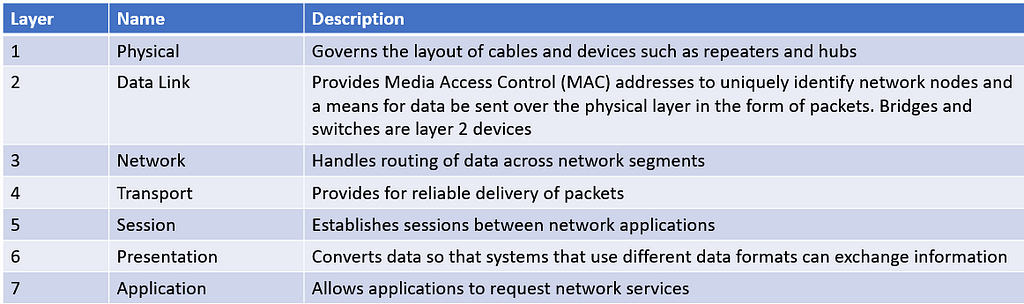
The First 3 layers deals with lower level mechanics of how information is sent from one computer to another over a network. Layer 4 to 7 are sometimes called upper layer. They deal with how application software can relate to the network through application programming interfaces
The seven layers of the OSI model are a somewhat idealized view of how networking protocols should work.
The Physical Layer
The bottom layer of the OSI model is the physical layer. It addresses the physical characteristics of the network, such as types of cables used to connect devices, the types of connectors used, how long the cables can be and so on.
Another aspect of the physical layer is the electrical characteristics of the signals used to transmit data over the cables from one network node to another. Physical layer doesn’t define any meaning to those signals other than the basic binary values of 1 and 0.
One type of physical layer device commonly used in networks is repeater, which is used to regenerate the signal whenever you need to exceed the cable length allowed by the physical layer standard. In olden days, there were hubs called multiport repeaters but they do not examine the contents of the packet that they regenerate
The network adapter (Network Interface Card) installed in each computer on the network is the physical layer device. You can display information about the network adapter installed in a windows computer by displaying the adapter’s properties
The Data Link Layer
The Data Link Later is the lowest layer at which meaning is assigned to the bits that are transmitted over the network. Data Link protocols address things such as the size of each packet of data to be sent, a means of addressing each packet so that it is delivered to the intended recipient and a way to ensure that two or more nodes don’t try to transmit data on the network at the same time.
The data link layer also provides basic error detection and correction to ensure the data sent is the same as the data received. If an uncorrectable error occurs,the data link standard must specify how the node is to be informed of the error so that it can retransmit the data
At the data link layer, each device on the network has an address: the MAC address. This address is hardwired into every network device by the manufacturer. MAC addresses are unique. The ipconfig command refers to the MAC address as the physical address.
One of the most important function of data link layer is to provide a way for the packets to be sent safely over the physical media without interference from other nodes attempting to send packets at the same time. The two most popular ways to do this are CSMA/CD ( Carrier Sense Multiple Access/Collision Detection)
Two types of data link layer devices are commonly used on networks —
- Bridge — An intelligent repeater that is aware of the MAC address of the nodes on either side of the bridge and can forward packets accordingly
- Switch — An intelligent hub that examines the MAC address of arriving packets to determine which port to forward the packet to
Another important Layer 2 concept is the idea of Virtual Local Area Network (VLAN) allow you to create separate isolated networks that share devices.
What is CSMA/CD?
It is important function of data link layer is to make sure that two computers do not try to send packets over the network at the same time. If they do, the signals will collide with each other, and the transmission will be garbled. Ethernet accomplishes this by using CSMA/CD
- Carrier Sense — Whenever the wants to send a packet over the network media. It first listens to the network media to see whether anyone else is already sending a packet. If it does not hear another signals on the media the computer assumes that the network is free, so it sends the packet.
- Multiple Access — Nothing prevents two or more devices from trying to send a message at the same time.
- Collision Detection — Device sends the packet, it listens carefully to see whether the packet crashes into another packet. If it hears then it waits a random period of time and then tries to send the packet again.
The Network Layer
The network layer handles the task of routing messages from one computer to another. The two most popular layer 2 protocols are IP(paired with TCP) and IPX( paired with SPX for use with Novell and Windows network)
Network Layer Protocol provide two important functions
- Logical Addressing —
Every network device has a physical address — a MAC address that is fixed and cannot be changed. Logical addressing comes in when you want to access a network device by using the addressing scheme you assign.
Logical Addresses are created and used by network layer protocols such as IP. The network layer protocol translates logical address to MAC addresses. Because the IP protocol must use a data link layer protocol to send packets to devices, IP must know how to translate the IP address of a device to device’s MAC address.
The logical address is divided into 2 parts —
- Network Address — Identifies which network the device resides on
- Device address — Identifies the device on the network
In typical IP address say 192.168.1.102 — the network address is 192.168.1 and the device address is 102.
- Routing —
Routing comes into play when computer on one netwrok needs to send a packet to a computer on another network. Router is used to forward the packet to the destination network. In some cases, packet may have to travel through several intermediate networks in order ot reach its final destination network.
An important feature of routers is you can use them to connect netwroks that use different later 2 protocols. As long as both networks support layer 3 protocol it does not matter whether their layer 1 and layer 2 protocols are different
A protocol is considered routable if it uses addresses that include a network part and a host part. Any protocol that uses physical addresses isn’t routable because physical addresses don’t indicate to which network a device belongs
The Transport Layer
The transport layer is concerned with the transportation of information from one computer to another.
The main purpose of the transport later is to ensure that packets are transported reliably and without errors. The transport later does this task of establishing connections between network devices, acknowledging the receipt of packets, and resending packets that are not received or are corrupted when they arrive
In many cases, the transport layer divides large messages into smaller packet that can be sent over the network efficiently. The transport layer protocol reassembles the message on the receiving end, making sure that all the packets that make up a single transmission are received so that no data is lost.
For some applications, speed and efficiency are more important that reliability. In such cases, a connectionless protocol can be used. A connectionless protocol doesn’t go to the trouble of establishing a connection before sending a packet, it simply send the packet. TCP is a connection oriented transport protocol. The connectionless protocol that works alongside TCP is User datagram Protocol (UDP).
We use netstat command to see the list of connections established
The Session Layer
The session layer established conversations — sessions — between networked devices. A session is an exchange of connection-oriented transmissions between two network devices. Each transmission is handled by the transport layer protocol. The session itself is managed by the session layer protocol.
A single session can include many exchanges of data between two computers involved in the session. After a session between two computers has been established, it’s maintained until the computers agree to terminate the session
The session layer allows 3 types of transmission modes:
- Simplex — Data flows in only one direction
- Half-Duplex — Data flows in both directions but only in one direction at a time
- Full Duplex — Data flows in both directions at the same time
The Presentation Layer
The presentation layer is responsible for how data is represented to applications. The most common representation for representing character data today is called UTF-8, which uses 8-bit sets to represent most characters foung in western alphabets. UTF-8 is compatible with an older standard called ASCII
UTF-8 is sometimes called Unicode, which is standard for representing the characters found in most of the world’s writing systems. Technically, UTF-8 is a particular method of implementing Unicode, so although the two terms are related, they are not identical
Some computers, in particular IBM mainframe computers, use a different code called Extended Binary Coded Decimal Interchange Code (EBCDIC). ASCII and EBCDIC are not compatiable. The presentation layer must conver the data when the information is exchanged between mainframe and desktop computers.
Along with simply converting the data from one code to another, the presentation layer can also apply sophisticated compression techniques so that fewer bytes of data are required to represent the information when it is sent over the network. At the end of transmission, the presentation layer then decompresses the data.
The presentation layer can also scramble the data before it is transmitted and then unscramble it at the other end by using a sophisticated encryption technique.
The Application Layer
The highest layer of OSI model, the application layer deals with the techniques that application program use to communicate with the network. The application layer represents the programming interfaces that application programs use to request network services.
Some application layer protocols are
- Domain Name System(DNS) — For resolving internet domain names
- File Transfer Protocol(FTP) — For file transfers
- Simple Mail Transfer Protocol(SMTP) — For email
- Server Message Block(SMB) — For file sharing in windows networks
- Network File System(NFS) — For file sharing in Unix networks
- Telnet — For terminal emulation
Following packets through Layers

The figure shows how a packet of information flows through the seven layers as it travels from one computer to another on the network. The data begins its journey when an end-user application sends data to another network computer. The data enters the network through an application layer interface, such as SMB. The data then works its way down the protocol stack. Along the way, tje protocol at each layer manipulates the data by adding header information converting the data into different formats, combining packets to form larger packets, and so on. When the data reaches the physical later protocol, it is placed on the network media and send to receiving computer.
When the receiving computer receives the data, the data works its way up through the protocol stack. Then, the protocol at each layer reverses the processing that was done by the corresponding layer on the sending computer. Headers are removed, data is converted back to its original format, packets that were split into smaller packets are recombined into larger messages, and so on. When the packet reaches the application layer protocol, it is delivered to an application that can process the data.
The Ethernet Protocol
Ethernet is the most popular set of protocols for the physical and data link layers. Various flavors of Ethernet operates at different speeds and use different types of media. However, all the versions of ethernet are compatible with each other, so that you can mix and match them on same network by using devices such as bridges, hubs and switches to link network segments that use different types of media
The actual transmission speed of Ethernet is measured in millions of bits per second(Mbps) or Billions of bits per second(Gbps). Ethernet comes in several different speed versions
- Standard Ethernet — 10Mbps , rarely used today
- Fast Ethernet — 100Mbps, Used for devices where speed is not important like printers or fax machines
- Gigabit Ethernet and beyond — 1000 Mbps, the most common speed used to connect user computers to a network. Faster speeds such as 10Gbps, 100 Gbps and even faster, are sometimes used in high-speed networks to connect servers and other critical devices to the network
Network transmission speed refers to the maximum speed that can be achieved over the network under ideal conditions. In reality, the actual throughput of ethernet network rarely reaches the maximum speed
Ethernet divides the data link layer into two separate layers: Logical Link Control (LLC) layer and Media Access Control (MAC) layer.
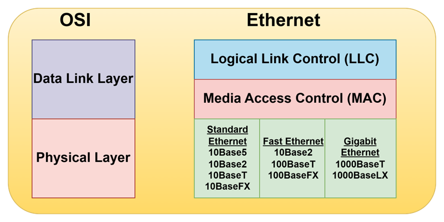
Standard Ethernet
Standard Ethernet is the original ethernet. It runs at 10 Mbps, which was considered fast in the 1970s but is excruciatingly slow by today’s standards. Depending on the type of cable used to string the network together
- 10Base5 — The original ethernet cable was thick, heavy and difficult to work with
- 10Base2 — The thinner type of coaxial cable. It uses bus topology
- 10BaseT — Unshielded Twisted Pair (UTP) cable became popular because its easier to install, lighter and more reliable and offers more flexibility in how networks are designed. It uses star topology with hubs at center of each star. Max length of 10BaseT is 100 meters, hubs can be chained to extend networks well beyond the 100-meter limit
Fast Ethernet
Ethernet that runs at 100Mbps, which is ten times the speed of Standard Ethernet. Although there are several varieties of Fast Ethernet, the most common is 100BaseTX, which transmits at 100Mbps over just two pairs of a UTP cable. 100Mbps Ethernet requires at least Cat-5 cable, but most networks are now wired with Cat-5e or Cat-6 cable, both of which are capable of gigabit speeds
Gigabit Ethernet
Gigabit Ethernet is Ethernet running at a 1000 Mbps or 1Gbps. Gigabit Ethernet once was expensive but now it is the standard for nearly all desktop and laptop PCs. Two grades of cable are commonly used: Cat-5e and Cat-6. Cat-6 can even be used for faster networks.
- 2.5GBase-T — 2.5 Gbps speed that can operate on Cat-5e cable.
- 5GBase-T — 5 Gbps speed that requires Cat-6 cable.
- 10GBase-T — 10 Gbps speed that requires Cat-6A cable.
- 25GBase-T — 25 Gbps speed that requires Cat-8 cable.
- 40GBase-T — 40 Gbps speed that requires Cat-8 cable.
There are many varieties of 10 Gbps, 40Gbps, 100 Gbps, 200 Gbps and even 400Gbps Ethernet that run on optic fiber cable.
10Base —
The cable designations consist of 3 parts:
- The first number is the speed of the network in Mbps. So, 10BaseT is for 10 Mbps
- Base is the short form on baseband indicates the type of network transmission that the cable uses. BaseBand transmissions carry one signal at a time and are relatively simple to implement. There is broadband which can carry more than one signal at a time but is more difficult to implement.
- The tail end of the designation indicates the cable type. For Coaxial cables, the number is used to indicate maximum length of the cable in hundreds of meters10Base5 can run up to 500 meters. 10Base2 cables can run up to 185 meters
The TCP/IP Protocol Suite
TCP/IP the protocol on which the internet is built, is not a single protocol but rather an entire suite of related protocols. TCP is even older than Ethernet.
The TCP/IP suite is based on a four layer model of networking similar to the 7-layer OSI model.

This figure shows how the TCP/IP model matches up with the OSI model and where some of the key TCP/IP protocols fit into the model. As you can see, the lowest layer of the model the network interface layer corresponds to the OSI model’s physical and data link layers. TCP/IP can run over a wide varierty of network interface layer protocols, including ethernet as well as other protocols, such as token ring and FDDI
The application layer of the TCP/IP model corresponds to the upper 3 layers of the OSI model — the session, presentation and application layers. Many protocols can be used at this level. A few of the most popular are HTTP, FTP, Telnet, SMTP, DNS and SNMP
The three most important protocols of TCP/IP Suite are
IP —
Internet Protocol (IP) is the network layer protocol responsible for delivering packets to network devices. The IP protocol uses logical IP addresses to refer to individual devices rather than physical (MAC) addresses. Address Resolution Protocol (ARP) handles the task of converting IP addresses to MAC addresses.
Because IP addresses consist of a network part and a host part, IP is a routable protocol. As a result, IP can forward a packet to another network if the host is not on the current network. After all, the capability to route packets across networks is where IP gets its name. An Internet is a just a series of two or more connected TCP/IP networks that can be reached by routing.
TCP —
Transmission Control Protocol( TCP) is a connection-oriented transport layer protocol. TCP lets a device to reliably send a packet to another device on the same network or different network. TCP ensures that each packet is delivered, if all possible , by establishing a connection with the receiving device and then sending the packets. If a packet doesn’t arrive, TCP resends the packet. The connection is closed only after the packet has been successfully delivered or an unrecoverable error condition has occurred.
One key aspect of TCP is that it’s always used for one-to-one communications. In other words, TCP allows a single network device to exchange data with another single network device. TCP is not used to broadcast messages to multiple network recipients. Instead, UDP is used for the purpose.
UDP —
User Datagram Protocol (UDP) is a connectionless transport layer protocol used when the overhead of a connection is not required. After UDP has placed a packet on the network ( via the IP protocol), it forgets about it. UDP doesn’t guarantee that the packet arrives at its destination. Most applications that use UDP simply wait for any replies expected as a result of packets send via UDP. If a reply doesn’t arrive within a certain period of time, the application either sends the packet again or gives up.
The best application layer protocol that uses UDP is the Domain Name System (DNS). When an application needs to access a domain name, DNS sends a UDP packet to a DNS server to look up the domain. When the server finds the domain, it returns the domain’s IP address in another UDP packet.
Happy Learning!!